A typical SAN presents block devices to a server, while NAS provides network file access. That is the starting distinction, regardless of the size or price of the storage appliance. Systems using similar SSDs and Ethernet hardware can still expose data at different layers.
For those who are studying storage for the first time and for operators who are designing virtualization infrastructure, it connects concepts, protocols, performance, redundancy, and recovery. Instead of distinguishing between ‘SAN is fast and NAS is slow’, we deal with the criteria for selection according to the work approach and failure conditions.
On this page
The first criterion to distinguish between SAN and NAS
SAN is a network that accesses storage.
SAN (Storage Area Network) is a network for storage devices that connects servers and storage. It consists of servers, switches, storage ports and devices, and in a typical block storage environment, the server recognizes the remote storage space as a block device similar to a local disk. When SAN is used to refer to just one storage entity, it is easy to miss network paths and host settings. SNIA’s SAN Description
Block is a method of reading and writing data in units of addresses of a certain size. The server can create a file system on the provided device, or use software that directly handles block devices, such as a database or volume manager. This can be understood as a structure in which storage provides logical space, and the server side decides how to use that space.
NAS provides file access services
NAS (Network Attached Storage) is a storage system that provides file access services over a network. Clients access the shared path using protocols such as NFS or SMB, and read and write data based on file name and directory. The file system and shared services are managed by the NAS. SNIA’s NAS definition
Personal 2-bay products are also NAS, and corporate file storage with multiple controllers and large capacity is also NAS. The name NAS alone does not determine its performance, level of redundancy, or maximum capacity. You need to consider the fact that the service is provided through NFS or SMB and the product level.
| Category | Typical block configuration using SAN | NAS file service |
|---|---|---|
| What is visible to the server | Block devices such as LUN and namespace | Shared folder/file/directory |
| File system management | Server, hypervisor, cluster software | NAS file system and file services |
| representative protocol | FC, iSCSI, NVMe/FC, NVMe/TCP | NFS, SMB |
| main access control | Host identifiers, mappings, fabric policies, etc. | Share permissions, file permissions, user authentication, etc. |
Both methods can co-exist in one device. In integrated storage that provides both file sharing and block services, you need to check the actual connection protocol rather than the brand of the device. However, providing both services does not mean that the same data can be safely modified in both ways at the same time. You must follow the data access model supported by your product.
The path that data takes, from server to disk
Default path in SAN
In an FC or iSCSI environment, the server-side request subject is called the initiator, and the storage-side provider is called the target. Requests go out from the server’s HBA or NIC and access storage space through switches and storage ports. LUN (Logical Unit Number) is a number that identifies a SCSI logical device, but in operations, the logical block device provided to the server is often called ‘LUN’.
The storage determines which devices to show based on the host identifier. You may encounter identifiers such as WWPN in FC and IQN in iSCSI. Even if the cable is connected, if the host mapping does not match, the device may not be visible on the server. Description of SAN configuration and host mapping for NetApp
| step | Role in block access | Points for operators to check |
|---|---|---|
| Application/file system | Use data as files or blocks | Delays, errors, mounts and device status |
| Host storage tier | Device requests and multipath processing | Driver, Path, Timeout |
| HBAs, NICs and switches | Storage traffic forwarding | Links, errors, congestion, reach |
| Storage port/controller | Device provisioning and I/O processing | Host mapping, ports, controller loading |
| Disk, flash, storage pool | Real data storage | Free space, media status, rebuild |
The hypervisor can take block storage and create a datastore, which can also store the VM’s virtual disk files. In this case, the disk seen by the guest OS and the actual SAN device are different layers. This is why when examining a guest’s disk latency, you should also look at the hypervisor and physical path.
Default path on NAS
In NAS, NFS/SMB requests from clients arrive at the file service over the network. The NAS checks user permissions and file/directory information before accessing the internal storage space. Clients usually do not directly manage the physical disks or RAID configurations inside the NAS.
Not all NAS failures are disk failures. If any of the following are out of sync: share name, DNS, authentication server, user ID mapping, file permissions, and network connection, the file may not open. If you determine that the file service is normal based solely on the result of ‘ping from the server’, it is difficult to find the cause.
How are FC, iSCSI, NFS, and SMB different?
Fiber Channel: Separate storage fabric
Fiber Channel (FC) is a connectivity technology used in enterprise SANs. A configuration using dedicated HBAs and FC switches is common, and storage traffic can be designed as a separate fabric from business Ethernet. Dedicated routes can help manage resources and fault coverage, but the costs of equipment and operational technology must also be considered.
The name FC does not refer to the optical cable itself. What matters is the transport technology and protocol, as well as the supported connection configurations. SNIA also explains that multiple protocols, including NVMe as well as SCSI, can be transmitted over FC. SAN’s connection technology and protocol
iSCSI: Connect block devices to IP networks
iSCSI is a method of transmitting SCSI commands to TCP/IP. Block storage can be connected using an Ethernet NIC and IP network. Therefore, if you classify it as ‘NAS because it is connected via a LAN cable,’ you will misunderstand iSCSI.
Even though existing Ethernet technology can be leveraged, production storage traffic requires bandwidth, path separation, drivers, and multipath design. The fact that a device is visible on the management screen is different from the judgment that stable operation is possible. You need to match the combination of host OS and storage provider support. Check SAN support configuration for ONTAP
NVMe over Fabrics: Extend NVMe commands to the network
NVMe/FC and NVMe/TCP are methods for delivering NVMe commands to FC- and TCP-based networks, respectively. The logical storage space provided to the host here is called NVMe namespace. Just because a device contains an NVMe SSD does not mean that it supports NVMe/TCP connectivity.
Separately check whether the medium is NVMe, what the internal connection is, and what protocol the host accesses. The OS, NIC/HBA, drivers, firmware, storage model, and software version must match. Actual support mix is verified against supplier matrix. NetApp’s NVMe configuration/constraints
NFS and SMB: Protocols for sharing files
NFS is widely used in file storage in Linux·Unix series and virtualization environments. Although SMB is closely related to Windows file sharing, it is not a protocol exclusive to Windows. Either way, you should check what protocol versions, authentication, locking, and encryption features the client and server support.
In an environment using NFS, the user/group ID, export policy, and authentication method are viewed together. In SMB, directory service integration, sharing permissions and file permissions, and signing/encryption policies are operational items. To provide the same shared folder through both protocols, it must be designed in a way that supports ID mapping and permission interpretation.
| way | units provided | connection based | Items to check upon introduction |
|---|---|---|---|
| FC SCSI block access | LUN | FC fabric | HBAs·Switches·Zoning·Multipathing |
| iSCSI | LUN | TCP/IP·Ethernet | NIC/IP path/host mapping/multipathing |
| NVMe/FC·NVMe/TCP | NVMe namespace | FC or TCP/IP | Version/Driver/Support Matrix |
| NFS | File/Directory | IP network | Version/Permission/Authentication/File Lock |
| SMB | File/Directory | IP network | Version, authentication, signing, encryption, availability features |
Both virtualization and database can be used
VMware: VMFS and NFS datastores
In a VMware environment, you can create a VMFS datastore on top of block storage or use an NFS share as a datastore. VMFS is a cluster file system that manages virtual machine files shared by multiple ESXi hosts. In an NFS datastore, the file service manages the file system, so there is no structure to reformat the NFS share to VMFS. ONTAP tools’ NFS·VMFS datastore description
When making a selection, compare existing operational capabilities, supported protocols, multipath and session configurations, backup integration, and data protection features of the storage. There is no basis to conclude that ‘since it is VMware, only SAN is possible’ or ‘if it is NFS, it is for development purposes’. However, it must be a combination supported by both the virtualization provider and the storage provider.
Hyper-V: SMB file shares also become VM storage
Hyper-V can be configured to store VM configuration, VHD·VHDX, etc. on supported SMB 3 file shares. Therefore, it cannot be considered unsuitable for virtualization work just because it is a file service. Microsoft covers SMB utilization with Hyper-V and SQL Server in their official documentation. Windows Server SMB and application storage
SMB Multichannel is a function that utilizes multiple connections, and SMB Direct is a function that uses RDMA. Not all NAS that support SMB meet all of these features and availability conditions for Hyper-V. You must separately check the NAS product’s certification, protocol implementation, and support for clients and network equipment.
Databases: Support and consistency come before connectivity
Whether to place the database on SAN or NAS depends on the DB product and version, certified file service, write consistency, and latency requirements. The name of a specific protocol alone does not guarantee synchronous write processing or recovery after failure. It is better to measure the I/O characteristics of log and data files in supported configurations.
The point at which the DB responds that the write is complete is also important. The configuration must ensure that records are preserved even during power failures as they pass through the application, OS, protocol, and controller caches. If you arbitrarily turn off safe write behavior to increase performance, you may change your data loss conditions, so you should follow your vendor’s recommendations and safeguards.
SAN is not always fast and NAS is not always slow
Performance comparisons include storage media, controllers, networks, clients, access patterns, and concurrency. Trying to explain the results between an all-flash NAS and an older disk-based SAN based solely on protocol differences would lead to an incorrect conclusion. Even on the same device, small random writes and large sequential reads are completely different loads.
View IOPS, throughput, and latency together
IOPS is the number of I/Os processed per second, and throughput is the amount of data delivered per second. Latency is the time it takes for one request to complete. Just because one of the three is high doesn’t mean the entire job will go faster.
As an example for calculations, if you process 4 KiB requests 100,000 times per second, the amount of data is approximately 390.6 MiB/s. Even for the same 100,000 IOPS, the throughput will vary if the request size changes. These figures are arithmetic examples showing unit relationships and are not measurements from specific equipment.
| indicator | Meaning when reading | Conditions to record together |
|---|---|---|
| IOPS | How many small requests do you handle? | Block size, read/write ratio, queue depth |
| throughput | How to transfer large data | File size, number of parallels, network utilization |
| average delay | overall response time | Load level and measurement interval |
| p95·p99 delay | How long do slow requests last? | Changes in timing of backup, rebuild, and failure |
A 10 Gb/s link divided by 8 is 1.25 GB/s in raw bit rate. This is a theoretical value without excluding protocol overhead, etc., and is not the same as the actual file transfer speed. If you start by comparing GB/s, GiB/s, and Gb/s without mixing them up, the performance numbers in the quote will become easier to read.
Match cache and working data sizes
Repeatedly reading only small data from the storage cache may produce better results than actual work. It should reflect the working set of operational data, read/write ratios, synchronous writes, and concurrent connections. Whether your data is well deduplicated and compressed may also affect the results.
It is better not to determine the size based on normal performance alone. We ensure that business goals are met even when rebuilding disks, resolving replication delays, and overlapping backups and controller maintenance. In particular, even if the average delay is okay, long delays in some requests can lead to user errors and timeouts.
Redundancy doesn’t end with two cables
SAN: Separate paths from hosts to controllers
Multipath I/O (MPIO) in SANs is a way for a host to manage multiple paths to a single logical device. In a supported configuration, when a path failure occurs, access continues through another path. ONTAP’s SCSI SAN description also covers path selection and failure handling through MPIO and ALUA. NVMe configurations require separate verification of the respective OS and vendor’s NVMe multipathing guidelines. Storage path failure handling
Even if there are two HBA ports, they can both be affected by the failure of the same card. Even if two switches are on the same power path, or if all cables are connected to the same single controller, a common point of failure remains. If you draw the connections between host ports, switches, storage ports, controllers, and power paths, any missing pieces will be revealed.
Ethernet link aggregation and MPIO also have different purposes and different operation layers. Link bonding does not replace configuring multipathing on a storage device. How bandwidth aggregation and fault switching behave on real I/O must be verified with a supported design.
FC zoning and LUN mapping are different access controls
FC zoning determines the range of ports that can communicate on a fabric. LUN mapping/masking determines which devices are presented to which hosts in the storage. If you assume that only one or the other setting is correct, your device may become invisible or exposed to unnecessary hosts. FC Zoning Concepts, SAN Host Mapping
Authentication and access control should also be distinguished from encryption. For example, you should not assume that just because you have iSCSI authentication set up, all data transfers are automatically encrypted. If there is a need for transmission protection, the design includes protocols and network support methods.
NAS: Check the availability of file services
In addition to redundancy of NICs and switches, the NAS also ensures file service failover, client reconnection, and file handle handling. Even if the IP responds again, this does not mean that all open files and application operations will be restored to normal. Behavior varies depending on NFS/SMB version, product features, and client settings.
Testing is performed at points of failure, such as cable breaks, switch maintenance, and controller switching. Whether you are reading a file, writing a large file, or whether the DB is performing a synchronous write also affects the results. The recovery time experienced by the operator includes both network recovery and application retry times.
Shared storage does not mean that all servers can use it at the same time.
Making the same block device visible to multiple servers is different from making the same block device visible to multiple servers. If a typical ext4·XFS file system for a single host is mounted simultaneously as read/write on the same device by multiple servers, metadata may be corrupted. Requires a supported cluster filesystem or shared disk structure for the application. Red Hat’s local/shared file system classification
Cluster file systems such as VMFS allow for multiple host access, but this does not mean that virtual disks of the same VM can be modified simultaneously by multiple guests. You must check the support conditions for multi-write functionality and guest clusters separately. We divide the sharing of the storage layer into the concurrency control of the application.
Although the NAS handles file access from multiple clients, it does not automatically resolve data conflicts from applications. The file locking method and DB operating conditions must match. The fact that multiple users can edit files in a shared folder should not extend to allowing multiple writes for all databases.
Kubernetes’ RWO·RWX is also read from the same perspective.
In Kubernetes, it is common to use block storage for reading and writing on a single node, and file storage for sharing across multiple nodes. However, the actual access mode is determined by the CSI driver and storage function, and it is not a fixed rule that ‘if it is a SAN, it is unconditionally RWO, and if it is a NAS, it is unconditionally RWX.’
ReadWriteOnce (RWO) is a mode that mounts as read/write on one node, and can be accessed by multiple Pods within that node. ReadWriteMany(RWX) indicates reading/writing from multiple nodes. Declaring an access mode alone does not prevent all write conflicts, and if you need a single Pod limit, you should look at separate conditions, such as ReadWriteOncePod in the supported CSI. Access modes of Kubernetes persistent volumes
Displayed capacity and actual usable capacity are different.
The raw capacity, which is the sum of the displayed capacity of the disk, is not the space that can be used at work. RAID or replication policies, spare space, metadata, snapshots, and operational redundancy must be considered. The standards for indicating usable capacity and efficiency application capacity may differ for each product.
As an arithmetic example, applying only RAID 6’s double-parity calculation to 8 identical 8 TB disks gives a nominal 48 TB. This excludes hot spares, metadata, filesystem overhead, unit differences and reserved capacity. Do not use that figure directly as a system’s recommended usable capacity.
Thin provisioning requires free space monitoring
Thin provisioning provides logical space first and then allocates physical space based on actual use. This can reduce initial waste, but if multiple volumes grow together, the physical pool may fill up first. You should monitor both the space remaining on the host and the space remaining in the storage pool. Storage Efficiency and Thin Provisioning
Snapshot archiving, replication delays, and the effects of compression and deduplication also change space usage. The fact that ‘the logical capacity has been made large enough’ is different from securing actual disk space. For tasks with large changes, you need to calculate not only the data growth but also the space held by snapshots.
The role of RAID, snapshots, replication and backup
RAID is used to tolerate a defined range of disk failures. It does not solve all user-deleted files, incorrect DB modifications, account takeovers, and site-wide failures. Even if the disk is healthy, your business data may be damaged.
Snapshots are useful for quickly returning to the state at a specific point in time. However, if you rely only on the same storage and the same administrator rights, you may be affected by equipment failure or breach. Since replication can also transmit incorrect changes to other systems, a system is needed to separately store and restore data from a normal point in time.
| means | mainly protective situations | Parts to prepare separately |
|---|---|---|
| RAID·Distributed replication | Failure of some disks and nodes | Deletion/Contamination/Disaster Recovery |
| snapshot | Return to a point in the near past | Storage space, permissions, and off-device recovery paths |
| remote replication | Maintain copies of other systems/sites | Replication delays, normal point-in-time retention, transitions |
| Separate backup | Past data and system restoration | Integrity verification, archival isolation, and restoration testing |
Ransomware response looks at separation of administrative rights, offline or appropriately isolated copies, and tamper-proof and deletion-proof storage. CISA also recommends offline/encrypted backup of important data and regular restoration verification. Don’t just look at the successful indication of the backup operation, you should check whether the necessary files and DB are opened normally. CISA Ransomware Response Guidelines
Recovery goals should also be determined in advance. RPO is the acceptable time frame for data loss, and RTO is the time objective that allows for business recovery. For example, ‘Tolerate loss of changes up to the last 15 minutes, resume work within 2 hours’ is an example goal for illustrative purposes. The actual goal is set with the person in charge and confirmed whether it has been achieved through a restoration test.
Which task should I choose?
If file paths and user permissions are central, such as shared documents, department files, or content storage, it may be a good idea to consider NAS file services first. This is because administrators can centrally manage shares, quotas, and permissions. If you have a large number of small files or large concurrent accesses, you should check both file services and metadata processing capabilities.
If the server needs to directly manage block devices and file systems, or if it needs to continue operating existing certified DB and virtualized SAN, block storage is the starting point. External SAN is not the only option at this time. Hyperconverged infrastructure or distributed storage can also provide block services, so we compare their overall operational structures.
| working conditions | Configurations to consider first | Conditions that can change your choice |
|---|---|---|
| User/department file sharing | SMB·NFS file service | Authentication/authorization, number of files, external collaboration method |
| Maintain existing SAN-based virtualization | Supported block datastores | Equipment replacement timing, backup, licensing, and operating technology |
| New design of virtualized storage | Comparison of block and NFS and supported SMB configurations | Platform authentication, failover, and management consistency |
| Low latency and stable writing of DB | Blocks or files supported by the provider | DB version, write protection, recovery/performance verification |
| Share files across multiple Kubernetes nodes | File/CSI configuration supporting RWX | Locking, drivers, throughput and access control |
| Long-term storage and access to large-scale objects | Also review object storage | API/Life Cycle/Application Compatibility |
Object storage is a separate model that focuses on buckets and object APIs. It is not meant to be an intermediate or higher tier between SAN and NAS. If the application requires a file system and only an object API is provided, it cannot be replaced immediately, so check the connection method first. Example of object/bucket access: Amazon S3
The estimate includes performance and recovery costs in case of failure.
SAN costs may include HBAs, switches, optical modules, and support contracts, while NAS may also require high-speed NICs/switches, controllers, authentication interconnection, and availability features. Costs vary depending on whether existing equipment can be reused and whether nodes, shelves, or ports must be added when expanding.
Quotation comparisons include not only normal usable capacity, but also performance when a component is missing, time required for recovery and re-protection, backup storage space, and operating personnel. Even if the unit price is low, if there is no restoration path or the target delay is exceeded in the event of a failure, the necessary business conditions will not be met.
Information to be left before operation begins
Recording only the device name makes it difficult to find the actual path in case of a failure. SAN stores host identifiers, device identifiers, zoning/mapping, and multipathing, while NAS stores shared paths, authentication, permissions, and service failover structures. Even if the person in charge changes, you must be able to find the path to recover data.
- Connect applications, data locations, protocols and personnel in one document.
- Steady-state latency, IOPS, throughput, headroom and number of errors are left as baseline values.
- Draw fault paths for hosts, switches, and controllers to identify common points of failure.
- Record supported OS, driver, and firmware combinations and update order.
- Restore data from a separate backup and verify application read/write.
- Manage the process of returning to the original path after a failure and the change history.
Rather than deciding between SAN and NAS first, check whether your business requires block devices or file sharing. Then, by matching the support configuration, behavior in case of failure, and restoration results, you can choose the storage you need without being swayed by the product name.
Official data and verification criteria
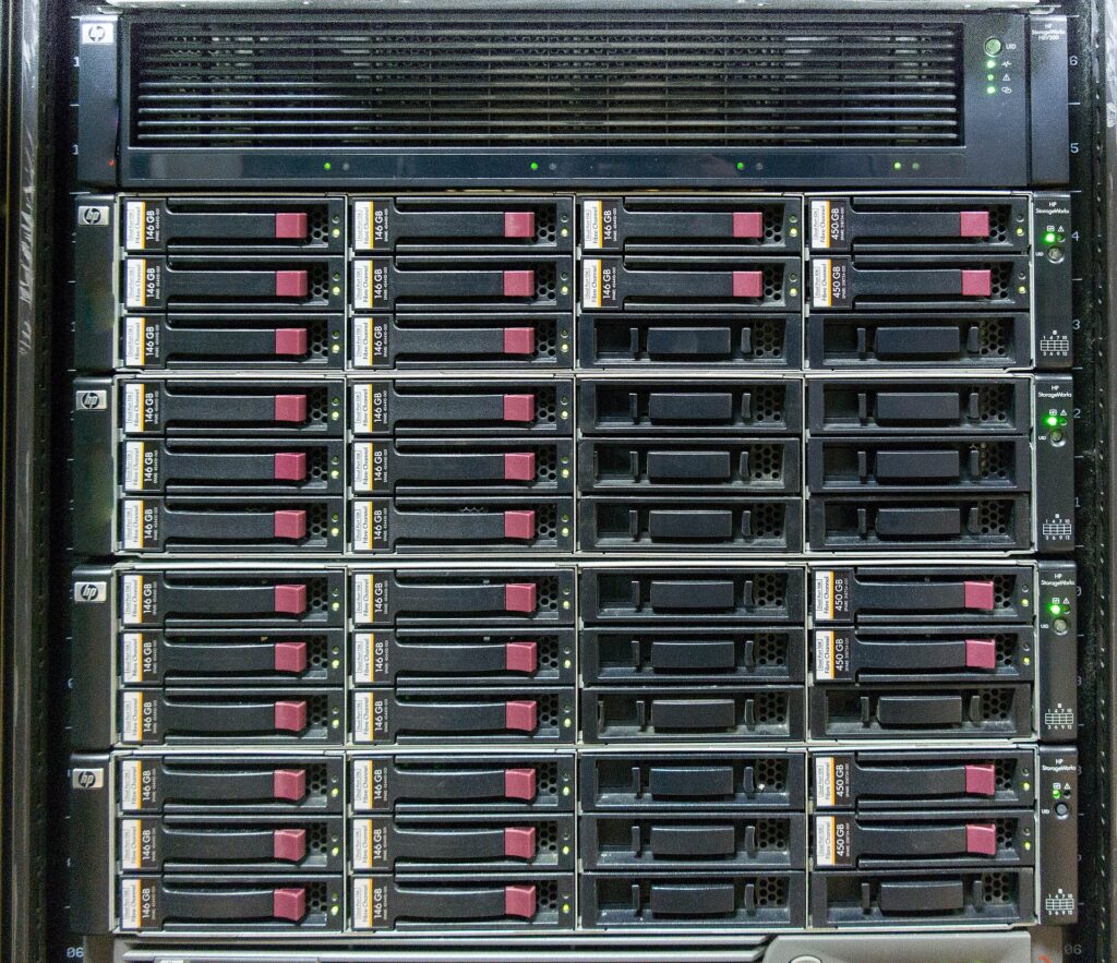
Concept and product documentation verified as of October 18, 2026. Calculation examples are intended to illustrate unit-capacity relationships and are not actual equipment benchmarks. The representative photo is a reference photo of HP EVA4400 equipment taken in 2014 and does not represent current product performance or the environment built in this article.
- SNIA: SAN concept and connection technology
- SNIA: NAS definition
- NetApp: SAN to host mapping
- NetApp: Configure SAN Support
- NetApp: NVMe configuration/support/constraints
- NetApp: NFS·VMFS datastore
- Microsoft: SMB file services and Hyper-V·SQL Server
- NetApp: Handling path failures
- NetApp: FC Zoning
- NetApp: Storage efficiency and space allocation
- Kubernetes: Persistent volumes and access modes
- CISA: Ransomware and backup/restore