Network layers become more useful when each one answers a concrete question: what the data means, which programs exchange it, how it crosses networks, how it reaches the next local device, and how bits become signals. This guide uses a five-layer TCP/IP teaching model to separate those roles and map them to the seven-layer OSI model.
First compare the OSI and TCP/IP layers, then follow a web request to its server. The examples explain the distinct roles of IP addresses, MAC addresses and ports, and the evidence to inspect when communication fails.
On this page
Why OSI has 7 layers and TCP/IP is taught with 4 or 5
Open Systems Interconnection (OSI) is a reference model that divides communication functions into seven layers. The purpose is to describe the communication functions of different systems in a common framework. The OSI model itself should not be viewed as identical to any one specific protocol used on the Internet. ITU-T X.200: OSI Basic Reference Model
RFC 1122, which describes the Internet Protocol structure, identifies the following layer distinctions: Application, Transport, Internet, and Link. The detailed requirements of the application layer here are covered in the companion RFC 1123. This distinction is the basis for the TCP/IP four-layer description. RFC 1122 §1.1.3
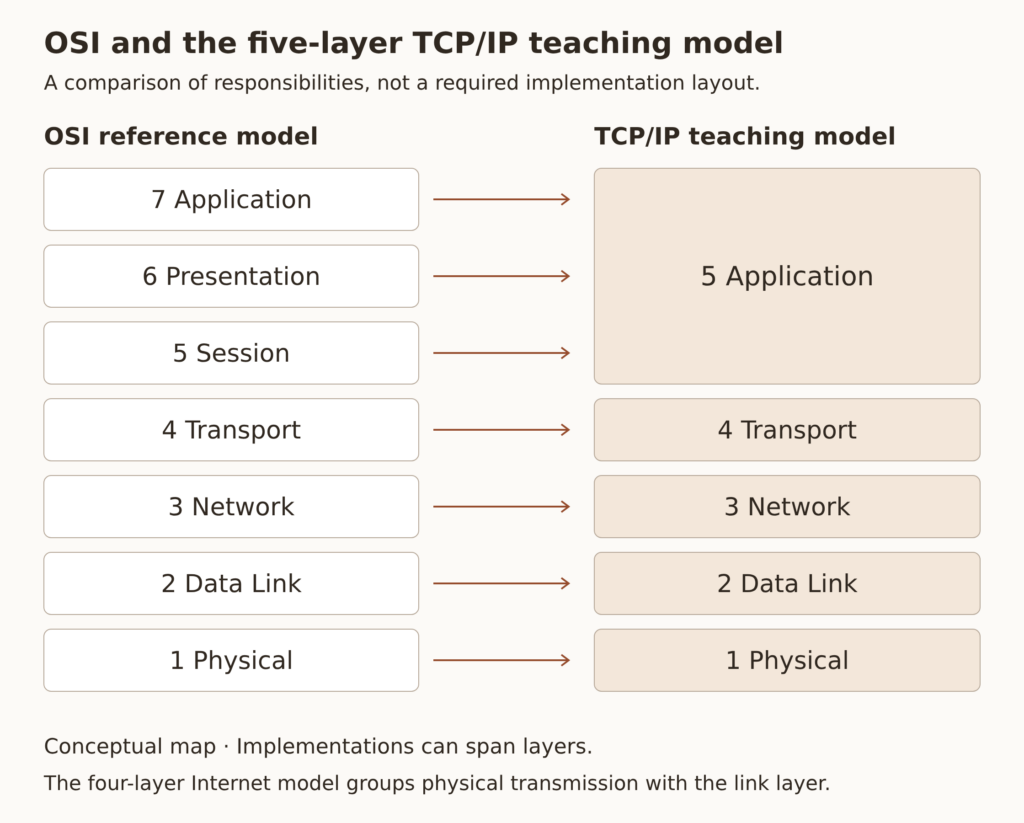
A common teaching model separates physical transmission from the link layer into 5 layers: Application → Transport → Network → Data Link → Physical. Kurose and Ross’s teaching materials distinguish these roles. This guide uses that model; it does not claim that the IETF defined it as the only standard 5-layer model. See Kurose and Ross: Internet protocol layers.
| Category | Hierarchy viewed from top to bottom | Purpose |
|---|---|---|
| OSI: 7 layers | Application · Presentation · Session · Transport · Network · Data Link · Physical | Reference model with detailed communication functions |
| TCP/IP: 4 layers | Application / Transport / Internet / Link | Internet Protocol Structure Description |
| TCP/IP: 5 layers in this guide | Application · Transport · Network · Data Link · Physical | Learning by dividing link transmission and physical signals |
The OSI application, presentation and session roles are grouped into application-side functions in the 5-layer teaching model. This compares responsibilities; it does not require every protocol implementation to map one-to-one to a box. A function can span libraries, an operating system and devices.
The roles of the seven OSI layers
The top three layers of OSI distinguish between what is communicated and how the conversation is expressed and managed. Going down the four layers, it becomes a question of transmission, path, link, and signaling. At first, it’s better to remember the questions the hierarchy answers rather than the specific product name.
| OSI layer | main role | Questions to help you understand | Corresponding role in the 5-layer model |
|---|---|---|---|
| 7 Application | Providing communication services required for application | What do you ask for and what response do you get? | 5 Application |
| 6 Presentation | Coordination of data representation and transmission format | Do you interpret the data with the same meaning? | 5 Application-side functions |
| 5 Session | Configuration, control and synchronization of conversations | How to start, manage and sync conversations | 5 Application-side functions |
| 4 Transport | End-to-end data transmission service | What transmission services do you provide? | 4 Transport |
| 3 Network | Delivery and routing across multiple networks | Which route leads toward the destination network? | 3 Network |
| 2 Data Link | Forwarding frames on one link | How does the frame reach the next device on this link? | 2 Data Link |
| 1 Physical | Signal transmission of electricity, light, wireless, etc. | What kind of signal is the bit sent through? | 1 Physical |
If you refer to the presentation layer as ‘a layer that only encrypts’ and the session layer as a ‘layer that stores login information,’ the scope becomes too narrow. The role of data presentation and conversation control comes first. Web login sessions, TCP connections, and OSI session layers may have similar names, but they are not the same thing.
Also, the application layer does not mean the browser’s buttons or the entire screen. We look at it in terms of the rules and services that applications use when communicating. Browsers use HTTP, but they do not put both screen rendering and user interface into the network layer model.
Connecting the five TCP/IP layers to real communication
Layer 5 Application: message meaning and communication rules
The application layer determines the format and meaning of messages sent and received by the program. On the web, you can encounter HTTP requests and responses, and in name lookups, you can encounter DNS queries and responses. SSH provides the communication rules necessary for remote access.
What is important in this layer is ‘what kind of request will the received byte be interpreted as?’ Even if they are connected to the same network, if the client and server expect different message formats, business will not be processed properly. This is why you need to distinguish between network connection success and application processing success.
It is also worth remembering that DNS is an application layer protocol. DNS is used to resolve IP addresses, but that does not make DNS itself a network layer protocol. Typical DNS communication uses TCP as well as UDP. There are configurations that use other delivery methods, such as encrypted DNS, so we do not assume that ‘DNS is always UDP 53’. RFC 7766: TCP support in DNS
Layer 4 Transport: end-to-end delivery and ports
The transport layer provides data delivery services for use by end-end programs. TCP and UDP use ports to distinguish multiple flows going to and from the same host. For example, TCP 443 and UDP 443 on a server are ports for different transport protocols, even though they have the same numbers.
TCP provides an ordered, reliable stream of bytes. It uses sequence numbers, acknowledgments, retransmissions, etc. and also performs flow control and congestion control. However, if the other party disappears for a long time or the network is disconnected, the connection may fail. Using TCP does not guarantee that a business request will be completed or executed only once. RFC 9293: TCP services and functions
UDP is a simple transport protocol that carries data in datagram units. UDP itself does not guarantee order restoration or retransmission like TCP does. Because applications or other protocols on top of UDP can implement the required functionality, you should not assume that the entire service has given up reliability simply because it uses UDP. RFC 768: UDP
| Category | TCP | UDP |
|---|---|---|
| Units provided to the application | ordered byte stream | datagram |
| Order/Resend | Provided by protocol | Not provided by UDP itself |
| Connection Management | Stay Connected | No connection establishment procedure like TCP |
| Judgment criteria | Design the necessary services and applications | Delay/loss handling and high-level protocol design |
The port number is only a clue to locating the service and is not a guarantee of identity. The server may be serving HTTPS on a different port, or there may be a different program running on port 443 than you expect. When looking at firewall and application settings, check the address, port, and protocol together.
Layer 3 Network: reaching other networks
At the network layer, we focus on IP addresses and routing. The host uses routing information to decide whether to send data to a directly connected destination or to the next router. The router selects the next route that matches the destination IP and forwards the packet.
IP provides best-effort delivery by default. IP itself does not provide all end-to-end retransmissions, ordering guarantees, and flow control. These functions are taken over by higher-level protocols such as TCP as needed. RFC 791: Scope and role of IP
There is also information that limits packets from continuing to circulate. IPv4 has a TTL and IPv6 has a Hop Limit, which decreases as it passes through the router. When the IPv6 router forwards and the result of reducing the Hop Limit becomes 0, the packet is discarded. ICMP and ICMPv6 are used for error reporting and diagnosis and are not protocols on top of TCP or UDP. RFC 8200: IPv6 Header
Layer 2 Data Link: reaching the next device
The data link layer is responsible for forwarding frames on one link. In Ethernet, information such as source and destination MAC addresses and EtherType are used in frames. The method of sending IP packets in the data part of the Ethernet frame is also connected to this layer. RFC 894: Forwarding IP datagrams over Ethernet
Here, the ‘destination MAC’ does not need to be the MAC of the server on the other side of the Internet. Communications to other networks usually send frames to the next hop on the current link, for example, the MAC of the default gateway interface. The final destination of the IP and the next partner on the link may be different.
A typical L2 switch forwards frames based on MAC address information. VLANs are used to logically divide L2 broadcast domains. However, a product called a switch does not necessarily perform only the L2 function; an L3 switch can also perform a routing function.
Ethernet’s FCS (Frame Check Sequence) is used to detect frame errors. Cisco’s Ethernet Frame and FCS Description Detecting errors and retransmitting lost data to the endpoint are two different functions. Wired Ethernet and Wi-Fi also do not have the same link behavior, so do not assume that all links will recover from failures in the same way.
Layer 1 Physical: carrying bits as signals
The physical layer is responsible for expressing and transmitting bits as signals such as electricity, light, and wireless. The conditions of cables, optical modules, connectors, wireless channels and physical interfaces are subject to inspection at this layer. A device called a NIC or switch port can contain both physical layer and data link layer functionality.
‘Link has been uploaded’ is an important clue to confirm physical connection. However, this alone does not mean that VLAN, IP, routing and applications are normal. Conversely, if the cable and signal are unstable, the service may be slow due to loss and retransmission even if the settings of the upper layer are correct.
Data is encapsulated, sent down, interpreted, and sent up.
Encapsulation is the process of storing data from the upper layer into the lower layer along with its own transfer information. In the example of transmitting TCP communication via Ethernet, a TCP header is attached to the application data, it is put into an IP packet, and then transmitted as an Ethernet frame. The physical layer transmits the information as a signal appropriate for the medium.
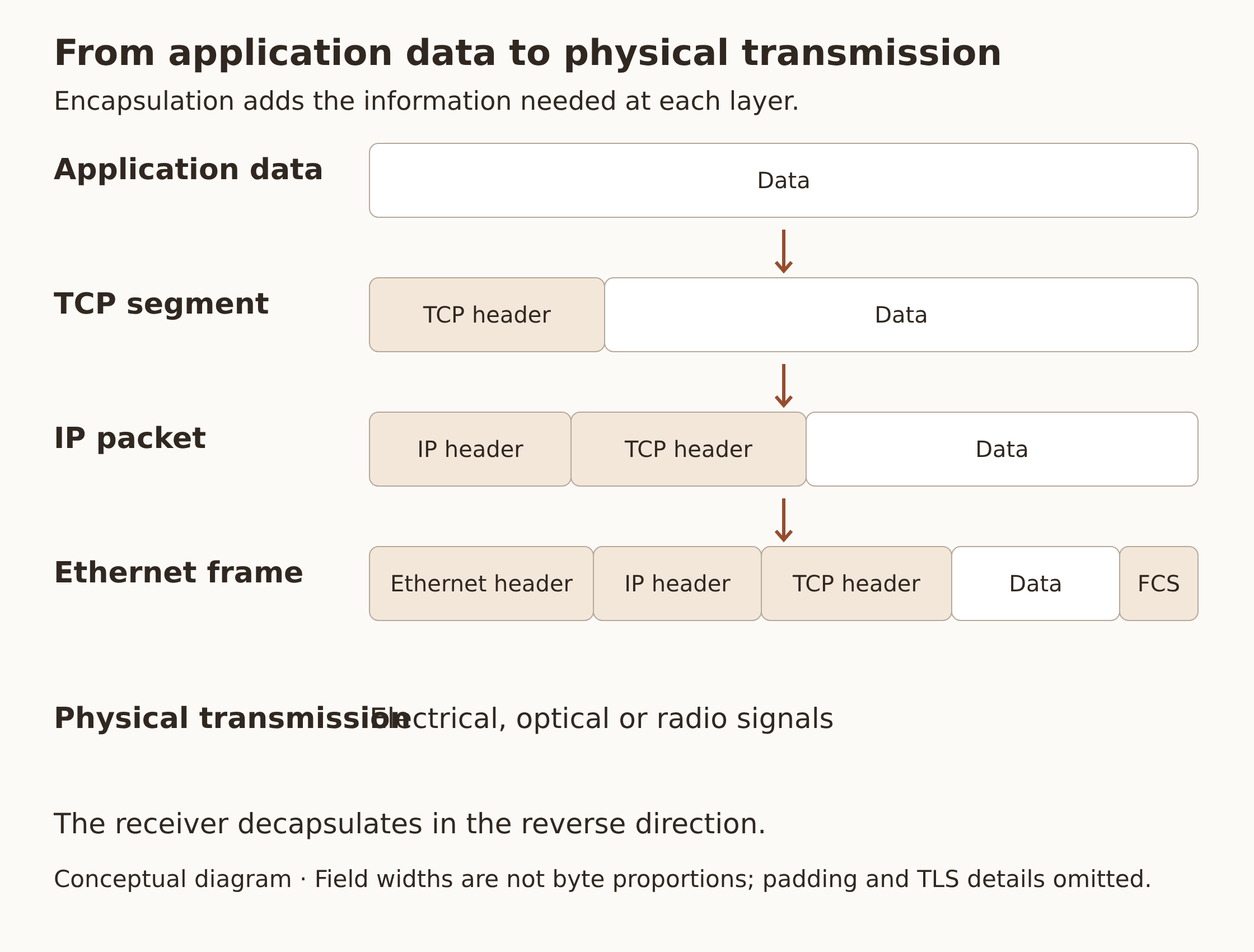
| processing steps | Examples of communication units | Information viewed at this stage |
|---|---|---|
| application | Message/Application Data | Request meaning, format, status code, etc. |
| TCP transport | TCP segment | Origin/destination port, order/confirmation information, etc. |
| IP network | IP packet/datagram | Origin/destination IP, next protocol, etc. |
| Ethernet link | Ethernet frame | Origin/destination MAC, EtherType, FCS, etc. |
| Physical transmission | Bit and signal flow | Signal method and media conditions |
PDU (Protocol Data Unit) refers to the protocol data unit handled by each layer. TCP uses the term segment, and UDP uses the term UDP datagram. Operators sometimes call various types of delivery units ‘packets’ for convenience, but when analyzing, it is better to distinguish which layer the unit belongs to.
The chunk of data in the picture is an example of the structure. A single actual HTTP request does not always fit into a single TCP segment or IP packet. Because TCP is a byte stream, the boundaries of application messages and segment boundaries may not match.
The receiving side goes through a process of interpreting the link, IP, and transmission information and passing it on to the upper level data. This is described as decapsulation. Since each layer checks conditions and errors, you should not judge that the data has been properly delivered to the application just because it has arrived.
Why distinguish between MTU and MSS
Link MTU is the maximum size of an IP packet, etc., that can be carried on that link at one time. TCP MSS indicates the maximum size of segment data excluding the TCP header. Assuming the Ethernet MTU is 1,500 bytes and there are only 20 bytes of IPv4 header and 20 bytes of TCP header, there is 1,460 bytes of space left for TCP data. This value is not the full length of the Ethernet frame.
In actual configurations, IP/TCP options, IPv6, MTU of tunnels and routes, etc. change the conditions. The presence of additional protocol information, such as TLS, also changes the amount of pure application data within TCP data. Rather than memorizing the value of 1,460 as a fixed value for all environments, it is more accurate to see which layer of information is subtracted from it. RFC 9293: MSS calculation
How are IP, MAC, and port used in one web request?
The example assumes IPv4 and Ethernet, with a TCP-based HTTPS connection to a web server on another network. Name resolution has already completed, traffic uses the default gateway, and NAT, proxies and VPNs are absent. This is a model for explaining the layers, not a packet capture from a measured connection.
First prepare to communicate with the gateway
The client checks the routing information and determines the next hop. In this example, since the destination server is outside the directly connected subnet, the default gateway is the next hop. If you do not know the Ethernet MAC of the gateway, you can use ARP to find out the MAC information corresponding to the IPv4 address. If it’s already in the cache, it won’t send a new ARP request every time. RFC 826: ARP
ARP is not a service that finds the MAC of a server across the Internet. Used to determine the relationship between the IPv4 address required for the current link and the link address. Since IPv6 uses ICMPv6-based Neighbor Discovery instead of ARP, the same commands and packet flows cannot be applied as is. RFC 4861: IPv6 Neighbor Discovery
After TCP connection and TLS negotiation, HTTP is exchanged.
The basic flow of creating a new TCP connection can be described as a three-way handshake: SYN, SYN-ACK, and ACK. A typical HTTPS new connection then performs TLS negotiation, verifies certificates, encryption conditions, etc., and then sends the HTTP request. This description assumes HTTPS over TCP and does not represent all procedures for connection reuse or other transport methods.
Looking at the first Ethernet section leaving the client, the purposes of the following three address information are different. The transport layer’s destination port points to the server’s receiving service, the IP destination points to the end server, and the Ethernet destination MAC points to the next hop on the current link.
| information | The destination for this example | Scope of application |
|---|---|---|
| TCP destination port | HTTPS listening port on the web server, usually 443 | Distinguish between transmission flow and reception service |
| IP destination address | IP of the final web server | Forwarding over the network |
| Ethernet destination MAC | MAC of the gateway currently on the link | Forwarding of the corresponding Ethernet link |
The router receives the IP packet from the incoming frame, determines the route, and forwards it to a new frame appropriate for the outgoing link. Therefore, a new link header is created in the section that passes through the router. If only general IP routing is performed and there is no conversion such as NAT, the source and destination IPs are maintained, but the TTL or Hop Limit may change. RFC 1812: Forwarding behavior of IPv4 router
Within the same VLAN, you must distinguish between when passing through a general L2 switch and when going through a router to another link. The explanation that ‘the destination MAC changes unconditionally every time you pass a switch or device’ is not accurate. Look at it based on the functions and boundaries it handles.
Avoid locking equipment and protocols to just one layer
Layer names describe responsibilities performed by equipment. A single device can handle multiple layers, and a tunnel can carry data from one layer within another protocol. So, if you only look at the product name and determine how the packet is processed, analysis becomes difficult.
| target | Starting point for reading the hierarchy | parts to see together |
|---|---|---|
| NIC/Switch Port | Physical signals and link frames | Link negotiation, errors, MAC·VLAN |
| Generic L2 switch | MAC-based frame forwarding | VLAN, bridge operation, management IP |
| Router/L3 switch | IP route and next hop | Interface physical/link conditions |
| Firewall/Load Balancer | Address, port, connection or application processing | Policies, state tracking, TLS termination or not |
TLS can be compared to the cryptographic role of the OSI presentation layer. However, if you fixate that ‘TLS exists exactly at OSI layer 6 in any implementation,’ it is difficult to explain the actual stack. In TCP/IP, it is better to look specifically at the relationship between higher-level protocol functions such as TLS and application protocols.
Even HTTP doesn’t always use TCP. HTTP/3 uses QUIC, and QUIC is a transport protocol that runs on top of UDP. Since QUIC provides functions such as stream, security, and loss handling, the conclusion that ‘there is no retransmission or reliability because it is on top of UDP’ is also incorrect. RFC 9114: HTTP/3, RFC 9000: QUIC
Narrowing down faults by layer
Even if a user says ‘the Internet is not working’, the actual causes are varied, such as signal loss, VLAN mismatch, missing route, port blocking, name lookup, TLS certificate and server error. The hierarchical model can be used as a framework to break down and identify these problems. Rather than always repeating the same sequence from bottom to top, it is more efficient to determine the next scope based on confirmed evidence.
| Symptoms Observed | What to check first | What should not be determined |
|---|---|---|
| Link is down | Cable, optical module, port, NIC, wireless connection | Assuming an IP address change will fix a physical link failure |
| Unable to communicate even with partners in the same VLAN | VLAN, MAC/ARP or ND, interface/address | Assuming L2 is healthy simply because a cable is connected |
| Gateway works, but remote service is not possible | Route, policy, return path, destination status | Determination that success of a local section means success of the entire route |
| IP communication works, but name lookup fails. | DNS server access and DNS response | Judgment that the entire network was disconnected |
| TCP connection works but HTTPS fails | TLS negotiation, certificate, server name, HTTP processing | Determination that successful port connection means success in web work |
| Ping fails, but web access succeeds | ICMP policy and service-specific acceptance conditions | Determination that the server is turned off based on ping failure alone |
A successful ping is evidence that the ICMP exchange is possible. This is not proof that HTTP requests, authentication, and DB queries are normal. Conversely, in an environment where ICMP is blocked, ping may not respond even if the web service is normal.
A single symptom can be affected by multiple layers. For example, loss due to physical-layer errors can increase TCP retransmissions, slowing down the application. It is better not to pin the cause on the application layer just because a timeout is stamped in the application log.
Three things to remember when you look at your next packet
If you see multiple addresses on the packet analysis screen, try distinguishing between ‘final destination IP’, ‘next partner MAC of current link’, and ‘port of transmission flow’. Next, check which protocol contains what and whether you are looking before or after the router. This will help you understand the actual delivery more directly than memorizing all the tier names.
Use the seven OSI layers to distinguish responsibilities in detail, and the five-layer TCP/IP teaching model to follow Internet communication. The same flow helps separate the roles of VLANs, routing and firewalls when studying them later.
Reference documents and illustrated guide
The source article checked the official standards and teaching materials on October 18, 2026. The English diagrams were rendered from code for this translation. They illustrate layer responsibilities and encapsulation; they are not packet captures or equipment measurements. Layer mappings and header order follow the explanation in the text.
- ITU-T X.200: OSI Basic Reference Model
- RFC 1122: Hierarchy of Internet hosts
- Kurose·Ross: Learning the roles of the five layers
- RFC 9293: TCP
- RFC 768: UDP
- RFC 791: IPv4 · RFC 8200: IPv6
- RFC 894: IP Encapsulation on Ethernet
- RFC 826: ARP · RFC 4861: IPv6 Neighbor Discovery
- RFC 7766: TCP support in DNS
- RFC 1812: IPv4 router requirements
- RFC 9114: HTTP/3 · RFC 9000: QUIC